Thursday, 7 October 2021

LOAD TEST ON A THREE PHASE TRANSFORMER

 AIM:

     To conduct a direct load test on the three phase transformer to determine the efficiency and regulation at different load conditions.

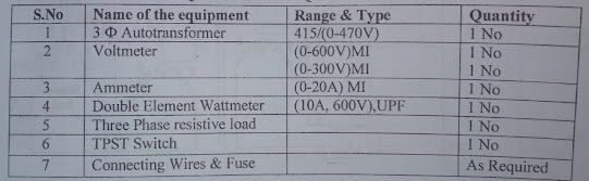
INSTRUMENTS AND EQUIPMENTS REQUIRED:

                       
INSTRUMENTS

THEORY:

      Large scale generation of electric power is usually 3-phase at generated voltages of 13.2KV or somewhat higher. Transmission is generally accompanied at higher voltages of 110, 132, 275, 400, and 750KV for which purpose 3-phase transformers are necessary to step up the generated voltage to that of the transmission line. Next, at load centers, the transmission voltages are reduced to distributed voltages of 6600, 4600 and 2300 volts. Further, at most of the consumers, the distribution voltages are still reduced utilization voltages of 440, 220 or 110 volts. Year ago, it was a common practice to use suitably interconnected three single-phase transformer. But these days, the latter is gaining popularity because of improvement in design and manufacture but principally because of better acquittance of operating men with three-phase type. As compared to a bank of single-phase transformers, the main advantage of a 3-phase transformer are that it occupies less floor space for equal rating, weight less, cost about 15% less and further, that only one unit is to be handled and connected.

PROCEDURE:

 1. The connections are made as per the circuit diagram.

 2. Keeping the autotransformer and load in its minimum position the main supply is switched ON by closing the TPSTS.

3. By slowly and carefully operating the autotransformer the rated voltage (415V) is applied to the primary side of the transformer.

4. Under this no-load condition one set of reading namely V1, W1, V2, I2 recorded in the tabular column.

5. Now the load is increases in gradual steps and at each step primary voltage is maintained at rated voltage and then all meter readings are noted down in the tabular column.

6. The procedure is continued until the current on the secondary side is equal to its full load value.

7. After the experiment is completed, the load is decreased to its minimum, the auto transformer is brought, back to its original position and then the main supply is switched OFF.

8. Calculate output power, efficiency and regulation.

CIRCUIT DIAGRAM:

                      
LOAD TEST ON A THREE PHASE TRANSFORMER CIRCUIT DIAGRAM

MODEL GRAPH:

                
LOAD TEST ON A THREE PHASE TRANSFORME MODERN GRAPH

If the above content is useful to you,  I am become very happy💖😀😀

Wednesday, 6 October 2021

NUCLEAR POWER PLANT-PART:3 - GAS- COOLED REACTOR

       The first gas-cooled reactors with CARBON-DI-OXIDE (at a pressure of 16 bar) as coolant and GRAPHITE as moderator were developed in Britain during 1956-69. The fuel was a NATURAL URANIUM, clad with an alloy of magnesium called MAGNOX.


gas cooled reactor

       Several types of gas-cooed reactor have been designed and built, with England developing an ADVANCED GAS-COOLED REACTOR (AGR) SYSTEM, and GERMANY and the USA developing HELIUM-COLED, GRAPHITE-MODERATOR SYSTEM  (HTGH). The AGR uses URANIUM OXIDE as the fuel clad in stainless steel tubes with CARBON-DI-OXIDE gas as coolant and graphite as moderator.

   The graphite moderator HELLIUM-COOLED HTGR is designed to use U-233 as the fissile material and thorium as fertile material. Initially, the system would have to be fueled with U-235, until sufficient U-233 is available for makeup fuel. Because of the very high melting point of graphite, these fuel elements can operate at very high temperatures, and it is possible to generate steam at conditions equivalent to those in modern coal-fired power plant. The basic fuel forms are small spheres of fissile and fertile material as carbide, URANIUM CARBIDE AND THORIUM CARBIDE. The fissile spheres are 0.35 to  0.5 mm in diameter and the fertile spheres are 0.6 to 0.7 mm in diameter. Each spheres is coated with two or three layers of CARBON  and SILICON CARBIDE to prevent fission products from escaping from the particles. HELIUM is a suitable coolant in sense that it is chemically INERT, as good heat transfer characteristic and low neutron absorption. Being an MONOATOMIC gas, it can produce for given temperature in the BRAYTON CYCLE and HIGH EFFICIENCY.

If the above content is useful to you, I am become very happy☝💖😀😀

Tuesday, 5 October 2021

NUCLEAR POWER PLANT- PART:2 - PRESSURIZED WATER REACTOR (PWR)

    The excellent properties of water as a moderator and coolant make it a natural choice for power reactor, and the PWR has been extensively developed in USA. The most important limitation in PWR is the critical temperature of water, 374* C. This is the maximum possible temperature of the coolant in the reactor, and in practice it is considerably less, possibly at about 300*C . In PWR, the coolant pressure must be greater than the saturation pressure at, say, 300*C (85.93 bar) to suppress boiling. The pressure is maintained at about 155 bar so as to prevent bulk boiling.


pressurized water reactor

   A PWR power plant is composed of two loops in series , the coolant loops called as the PRIMARY LOOP, and WATER- STEAM or WORKING FLUID LOOP. The coolant picks up heat in the reactor and transfers it to the working fluid in the steam generator. The steam is then used in a Rankine type cycle to produce electricity.

    The fuel in PWR is slightly ENRICHED URANIUM in the form of thin rods or plates. The cladding is either of stainless steel or zircaloy. because of very high coolant pressure, the steel pressure vessel containing the core must be about 20 to 25  cm thick. A typical PWR contain  about 200 fuel assemblies , each assembly being an array of rods. In a typical fuel assembly, there are 264 fuel rods and 24 guide tubes for control rods. Grid spacers maintain a separation between the fuel rods to prevent excessive vibration and allow some axial thermal expansion.

   The coolant leave the reactor and enter the steam generator which can be either shell and tube type with U- tube bundles or once-through type, the former being more common. In the U- tube steam generator, the hot coolant enters an inlet channel head at the bottom, flows through the U-tubes, and reverse the direction to an outlet at the bottom. It can produce only saturated steam. In the once-through design, the primary coolant enters at top, flows downward through tubes and exits at the bottom to the main pumps. feedwater is on the shell side. A dry or low degree of superheat stream is possible.

    The first land based PWR for power generation was built at SHIPPINGPORT, USA in 1957. Its thermal output is 231 MW, the pressure in the primary circuit is 141 bar, and the water temperature at outlet from the reactor is 283*C . Dry saturated steam is generated in the heat exchangers at 41 bar, 252*C. For a gross electrical output of 68 MW, the efficiency is 29.4%.


pressurized water reactor

   The shippingport cycle has been modified in the Indian point (USA) PWR by the inclusion of an oil-fired superheater between the main heat exchangers and the turbines. There is also an economizer along with some feedwater heaters. The steam condition improves to 25.5 bar and 538*C at turbine inlet, and so the cycle efficiency increases.

If the above information is useful, I am become very happy☝💖😀😀

Monday, 4 October 2021

NUCLEAR POWER PLANT - PART:1 - COMPONENTS

 INTRODUCTION:

      Nuclear power plants are a type of power plant that use the process of nuclear fission in order to generate electricity. They do this by using nuclear reactors in combination with the Rankine cycle, where the heat generated by the reactor converts water into steam, which spins a turbine and a generator.

COMPONENTS OF NUCLEAR REACTOR:

nuclear power plant


MODERATOR:

 The moderator of a nuclear reactor is a substance that slows neutrons down.  When fast neutrons strike the hydrogen atoms in H2O, they slow down. eg-  graphite, beryllium, Heavy water, Normal water, Helium gas.

PROPERTIES:

 1. It should have high thermal conductivity.
 2. It should have high corrosion resistance.
 3.It should lighter in weight.
 4. It should has good stability to heat and power radiation.

CONTROL RODS:

  It use to control the incidence of the neutrons and prevent the nuclear reactor from the explosions.

FUNCTION OF CONTROL RODS:

 1. To control the rate of fission.
 2. To start the nuclear chain reaction when the reactor is started from cold.
 3. To shunt down the reactor in the emergency condition.
 4. To prevent the melting of fuel rods.

CONTROL RODS SHOULD POSSES THE FOLLOWING PROPERTIES:

 1. It should have good stability under heat and radiation.
 2. It should have adequate heat transfer properties.
 3. It should have better corrosion resistance.

BORON, CADMIUM, HAFNIUM ARE MOSTLY USED AS  CONTROL RODS.

REFLECTOR:

 1. Reflector materials placed around the core to reflect back some of neutrons that they leak- out from the surface of the core.

 2. The reflected neutrons cause more fission and they improve the neutrons economy of reactor.
 3. It made as same material as moderator.

HEAVY WATER, NORMAL WATER, BERYLLIUM, GRAPHITE, HELIUM GAS.

COOLING SYSTEM:

   The coolant are used to carry away heat produced inside the reactor to the heat exchanger. From heat exchanger , heat is transferred to another working medium for further utilization of power generation.

NORMAL WATER, GASES , LIQUID METALS ARE USED.

PROPERTIES:

 1. It should have low melting point.
 2. It should have low viscosity
 3. It should be Non - Corrosiveness.
 4. It should have high density.
 5. It should have high specific heat.

BIOLOGICAL SHIELDING:

     Shielding is necessary to protect the walls of the reactor vessel from radiation damage and it protect the operation personnel from exposure to radiation.
 1. Thick layer of lead concrete or steel are provided all around the reactor.
 2. These layer absorbs the gamma rays, neutrons, etc.,

A GOOD SHIELDIG MATERIALS SHOULD HAVE THE FOLLOWING PROPERTIES:

 1. It should absorb Alpha, Beta and Gamma radiation.
 2. It should have uniform density.
 3. It should be fire resistance.


HEAT EXCHANGER:

  It is used to convert feed water into stream from heat produced in a nuclear reactor core.

STEAM TURBINE:

  A steam turbine is a device that extracts thermal energy from pressurized stream and uses it to do mechanical work on a rotating output shaft.


GENERATOR:

  A generator is a device that convert mechanical energy of the steam turbine to electrical energy.


 If the above information is useful to you, I am become very happy😀😀💖☝👍

Sunday, 3 October 2021

PARALLEL OPERATION OF TRANSFORMERS

          The transformers are connected in parallel when the load on them is more than the rating of the individual transformers.so several smaller units are connect in parallel


parallel operation of transformer

          from the above diagram, it can be seen that the primary winding are connected to the supply bus bars while the secondary winding are connected to load bus bars.

          Thus two or more transformers are connected in parallel to carry common load. If the given transformer is insufficient in capacity to deliver a particular  load it may replaced by the larger unit or an additional unit. Then the primary side is connected to the same supply and the secondary side is connected to the same load circuit.


parallel operation of transformer


         From the above diagram , It is the another form of parallel operation. The difference from the previous  diagram is that the two units are first connected together and then connected to the respective supply and load circuit.

ABOVE TWO FORMS ARE APPLICABLE IN PARALLEL OPERATION OF TRANSFORMERS .☝☝

CONDITION FOR SATISFACTORY PARALLEL OPERATION:

 1. The transformers are connected with same polarity. In case of three phase transformers should have same angular displacement and same phase transformers.

 2. The voltage ratio of primary and secondary are should be same.

 3. The  frequency ratio primary and secondary must be same.

 4. Percentage impedance must be equal to magnitude.

If the above content is useful to you, I am very happy👍😀😀💖

LOAD TEST ON A THREE PHASE TRANSFORMER

 AIM:       To conduct a direct load test on the three phase transformer to determine the efficiency and regulation at different load cond...