AIM:
To conduct a direct load test on the three phase transformer to determine the efficiency and regulation at different load conditions.
INSTRUMENTS AND EQUIPMENTS REQUIRED:
THEORY:
Large scale generation of electric power is usually 3-phase at generated voltages of 13.2KV or somewhat higher. Transmission is generally accompanied at higher voltages of 110, 132, 275, 400, and 750KV for which purpose 3-phase transformers are necessary to step up the generated voltage to that of the transmission line. Next, at load centers, the transmission voltages are reduced to distributed voltages of 6600, 4600 and 2300 volts. Further, at most of the consumers, the distribution voltages are still reduced utilization voltages of 440, 220 or 110 volts. Year ago, it was a common practice to use suitably interconnected three single-phase transformer. But these days, the latter is gaining popularity because of improvement in design and manufacture but principally because of better acquittance of operating men with three-phase type. As compared to a bank of single-phase transformers, the main advantage of a 3-phase transformer are that it occupies less floor space for equal rating, weight less, cost about 15% less and further, that only one unit is to be handled and connected.
PROCEDURE:
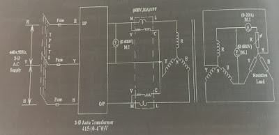
1. The connections are made as per the circuit diagram.
2. Keeping the autotransformer and load in its minimum position the main supply is switched ON by closing the TPSTS.
3. By slowly and carefully operating the autotransformer the rated voltage (415V) is applied to the primary side of the transformer.
4. Under this no-load condition one set of reading namely V1, W1, V2, I2 recorded in the tabular column.
5. Now the load is increases in gradual steps and at each step primary voltage is maintained at rated voltage and then all meter readings are noted down in the tabular column.
6. The procedure is continued until the current on the secondary side is equal to its full load value.
7. After the experiment is completed, the load is decreased to its minimum, the auto transformer is brought, back to its original position and then the main supply is switched OFF.
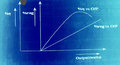
8. Calculate output power, efficiency and regulation.


No comments:
Post a Comment