Tuesday, 27 July 2021

NODAL ANALYSIS


 USES OF NODAL ANALYSIS :

       It is an important technique to finding solution in a network

ABOUT NODE :

 Three or more branches connected at a point is called as node point or node.

STEPS INVOLVES IN NODAL ANALYSIS :

STEP - 1 : Find the all nodal points and choose one point as a reference point.

STEP - 2 : Label the node voltage and mark current.

STEP - 3 : Apply Kirchhoff's current law at node point.

NOTE :

Node voltage is obtain by below pneumatics.

Node voltage = Voltage at arrow tail - Voltage at arrow head


arrow diagram

APPLICATION OF NODAL ANALYSIS :

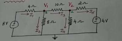
Determine the current through 10 ohm resistor.


question

STEP - 1 : There are three nodal point in the above circuit.

STEP - 2 :Mark the nodal point and current.


circuit

STEP - 3 : Apply Kirchhoff's current law at each node point.

       At Node V1 :

              I1 - I2 - I3 = 0                                                                               -----> 1

      Get the value of current refer notes,

             I1 = 8 - V1/4 , I2 = V1 - 0/8 , I3 = V1 - V2/10

        Substitute the current value in equation 1

           ((8 - V1)/4) - (V1/8) - ((V1 - V2)/10) =0

            0.475 V1 - 0.1 V2 = 2                                                                  ------> 2

       At Node V2 :

                I3 - I4 - I5 =0                                                                              ------> 3

     Get the value of current refer notes,

            I3 = V1 - V2/10 , I4 = V2 - 0/4 , I5 = V2 - 4/2

      Substitute the value of current in the equation 3

            ((V1 - V2)/10) - ((V2 - 0)/4) - ((V2 - 4)/2) = 0

             0.1 V1 - 0.85 V2 = -2                                                               ------> 4

       Solving the equation 2 and 4, we get

               V1 = 4.825 V , V2 = 2.920 V

        For the current at 10 ohm,

           I10 ohm = ((V1-V2)/10) = ((4.825 - 2.920)/10) = 1.905/10 = 0.1905 ohm.

IN THIS WAY WE USE THE NODAL ANALYSIS.


Monday, 26 July 2021

MESH ANALYSIS

 USES OF MESH ANALYSIS :

       It is an important technique to finding solution in a network.

ABOUT MESH ANALYSIS :

1. If the network has a large number of voltage source , the mesh analysis is applicable.

2. If there is a current source then it will convert into voltage source for apply mesh analysis.

3. The mesh analysis s only applicable to the planar circuit .

        Example of planar circuit :-

PLANAR CIRCUIT

        Example of Non Planar circuit :- 

NON PLANAR CIRCUIT

STEPS INVOLVES IN MESH ANALYSIS :

  Step - 1 :  To find whether the circuit is planar or Non - Planar.

  Step - 2 :  Select the mesh current.

  Step - 3 : Using the Kirchhoff's voltage law to get the equation in terms of unknown to solve the problem.

NOTE :

No . of Equation = No . of mesh current

APPLICATION OF MESH ANALYSIS :

Write the MESH CURRENT equation in the circuit.


CIRCUIT DIAGRAM

STEP - 1 : The above circuit is planar.

STEP - 2 :  The selected mesh currents are  I1 and I2

STEP - 3 :  Using the Kirchhoff's' voltage law

          There are two loops in the above circuit. so, apply law in both first loop and second loop . The equation is

                      5 I1 + 2( I1 -I2 ) = 10

                      10 I2 + 2 ( I2 -I1 ) + 50 =0                                                   

          The following equation is

                       7 I1 - 2 I2 = 10                                                                     ----> 1 

                        -2 I1 + 12 I2 = -50                                                             -----> 2

        By solving the above equations , we have

          I1 = 0.25 A   ,    I2 =  -4.125 A

ANSWER THE QUESTIONS :

1. If the circuit is planar then which analysis is preferable ?

2. MESH ANALYSIS need which source ?

3.  Number of equation is equal to ?   

Saturday, 24 July 2021

ORANIC LIGHT EMITTING DIODE ( OLED )

                           
OLED

 PRINCIPLE :

            It is the solid state device made up of thin films of organic molecules that produce light with the application of electricity. An electron moves from the cathode to the emissive layer ( ELECTRON TRANSPORTING LAYER ) and the hole moves from the anode to the conductive layer (HOLE INJECTIVE LAYER ) and they recombine to produce photon ( Light ). 

STRUCTURE : 

1. The OLED consist of a cathode and a anode, in between there are two organic layers present

2. The layers are emissive layer (ELECTRON TRANSPORTING LAYER ) and Conductive layer   (HOLE INJECTION LAYER )

3. All the layers are grown over a transparent substrate through which the light will be emitted.

4. ANODE is connected to the positive terminal and CATHODE is connected to the negative terminal of the battery.


OLED

WORKING :

1. Forward bias voltage is applied across the OLED.

2. By apply voltage to the cathode will get negative charge electrons. Then the electrons in the cathode will repel  the electrons in the next layer i.e. (ELECTRON EMITTING LAYER).

3.By apply voltage to the anode will get positive charge holes. Then the holes in the anode will repel the holes in the previous layer i.e. (HOLE INJECTING LAYER ).

4.By the electrostatic force the electron in the ELECTRON EMITTING LAYER attract the holes in the hole injection layer and the recombination take place in the organic emitters .

5. The recombination take place near to the emissive layer of the organic emitters because the movement of the hole is faster in the organic semiconductor.

6.The recombination is result in the production of POTON (Light).The light is pass through the transparent substrate.


OTHER DETAILS :

  • OLED is made up of 100 to 500 nm thick.
  •  The Organic Light Emitting Diode (OLED) is also called Light Emitting Polymer (LEP) or Organic Electro Luminescence (OEL) and it consist of a film of organic compound.
  • eg of ELECTRON TRANSPORTIN LAYER - POLYFLURENE
  • eg of HOLE INJECTION LAYER - POLYANILINE 

Thursday, 22 July 2021

SOLAR CELL OR PHOTOVOLTAIC CELL

CONSTRUCTION AND FUNCTION OF SOLAR CELL 

 BELOW  QUESTIONS  GIVE THE ANSWER TO THE FUNCTION OF THE SOLAR CELL 

1. How to make a  N - type semiconductor ?

        In the normal silicon material the doping is take place with the pentavalent  atoms like PHOSPHORUS  . In this type of semiconductor  electrons are the majority charge carriers .


N - TYPE SEMICONDUCTOR

2. How to make a  P - type semiconductor ?

        In the normal silicon material the doping is take place with the Tetravalent atoms like BORON. In this type of semiconductor Holes are the majority charge carriers.
                    
P - TYPE SEMICONDUCTOR

3. What will happen when the light is fall on the  N - type semiconductor ?

         When the light fall on the  N - type semiconductor, the bond brakes to the extra electron present in the atoms which are loosely  bonded. So the electrons are random in motion.

4. What will happen when both  P - type and  N - type are combines ?

        When we combine both types of semiconductor , the electrons in the  N - type is combine with the holes in the  P - type by the driving force . It produce the depletion  region in the          middle  
driving force


5. What is the depletion layer ?

         It is the region , in which there is no free electrons and holes.
                        
DEPLETION REGION

6. What happen when the light fall on the depletion layer ?

        When light fall on the depletion region, leads to the generation of ELECTRON - HOLE pair.
                         
ELECTRON - HOLE PAIR

CONSTRUCTION :

1. Place a thin heavily doped  N - type material at the top .
2.Place a thick lightly doped  P - type material at the bottom.
3. Both the  P - type and  N - type are packed in a can with glass window on top.
4. A nickel ring is provided around the  P - type is act as positive terminal.
5. A metal is contact with the  N - type is act as negative terminal .

FUNCTION :

      When the light is fall on the depletion region it generate the ELECTRON - HOLE pairs which create the potential difference which produce the DIRECT CURRENT to flow in the load.(refer above questions)

Wednesday, 21 July 2021

CONSTRUCTION OF LED

 SUBSTRATE MATERIAL - The materials are sapphire, SiC etc.

 SEMICONDUCTOR MATERIAL - Indium gallium nitride (InGaN) for Blue, Green, Ultraviolet high brightness LEDs. Aluminum gallium indium phosphide (AlGaInP) for Yellow, Orange, Red high brightness LEDs.

CONSTRUCTION :

      1. A  n - type semiconductor layer is placed on the substrate .

      2. A   p - type semiconductor layer is placed on the  n - type layer by diffusion .

      3. The carrier charge recombination is take place in the  p - type layer . So, the  p -type layer is placed on the TOP.

     4. For the maximum light emission , a metal film (aluminum) anode is placed at the outer edges of the  p - type layer.

     5. The bottom of the substrate  is coated with the metal film (gold) for to reflect most of the light to the surface of the device and provide the cathode connection.

       The above points will give the basic idea about the construction of LED.

                             CONSTRUCTION OF LED


Tuesday, 20 July 2021

VAPOUR ABSORPTION REFRIGERATION SYSTEM

 PRINCIPLE : 

                           The vapour absorption system has no compressor. The compressor is replaced by the combined effects provided by an Absorber , Pump and Generator. The compressor work is replaced by the heat supplied in the generator and pump. The pump consumes less electric power. The generator is operated by the external heat source. 


ABSORBENT - It absorbs refrigerant in the vapour phase and convert into liquid phase. 

REFRIGERANT - Ammonia is used as the refrigerant. 

AQUA - AMMONIA SYSTEM - It used the homogenous mixture of ammonia and water. Hence it is called as aqua-ammonia system.

 DESCRIPTION :

                EVAPORATOR - It consist of coiled tubes. The substance to be cooled is paced in the evaporator. It is the coldest region in the refrigerator. It is also called refrigerated space or freezer compartments.

               ABSORBER TANK - It contain the absorbent. It should have high affinity for the refrigerant, high boiling point and low specific heat.

               CIRCULATION PUMP- The pump circulates the refrigerant to the generator.

               GENERATOR - Heat is added to the generator from an external source. It may be a gas burner or solar heater.

               CONDENSER - Air or water is used as the cooling medium.

                  EXPENSION VALVE - The condenser is connected to an expansion valve. The pressure of the liquid passing through the expansion valve drops for reuse in the evaporator.

WORKING :

  • The dry low pressure ammonia vapour from the evaporator enters the absorber.
  • The absorber contain the cold water. Dry ammonia vapour is absorbed in the cold water producing a low pressure concentrated ammonia solution.
  • The circulation pump pumps the strong ammonia solution from the absorber to the generator. This action increase the pressure of the solution.
  • In the Generator, the solution is heated by external heat source (solar).
  • Hence the high pressure ammonia vapour enters the condenser (concentrated ammonia solution).
  • The weak ammonia solution in the generator come back to the absorber. 
  • In the condenser, cold water is circulated around the condenser tubes. So the ammonia vapour is condensed to liquid ammonia.
  • The high pressure liquid ammonia is passed to the expansion valve for reduce the pressure.
  • The low pressure low temperature Ammonia liquid is passed to the evaporator in the freezer compartment . 
  • The resultant ammonia vapour from the evaporator to the absorber.                               VAPOUR ABSORPTION REFRIGERATION SYSTEM

Monday, 19 July 2021

Fleming's Right Hand Rule & Fleming's Left Hand Rule

    FLEMING'S LEFT HAND RULE

                  Stretch out FOREFINGER, MIDDLE FINGER  and THUMB of the left hand such that they are in three mutually perpendicular direction . If the forefinger point in the direction of magnetic field, the middle finger in the direction of the electric current , then thumb will point the direction of the force experienced by the conductor.

Fleming's left hand rule

     FLMING'S RIGHT HAND RULE

                  The THUMB, INDEX FINGER and MIDDLE FINGER of right hand are stretched out in mutually perpendicular direction . If the index finger point the direction of the magnetic field and the thumb indicates the direction of motion of the conductor, then the middle finger will indicate the direction of the induced current.

Fleming's right hand rule

Saturday, 17 July 2021

VAPOUR C0MPRESSION SYSTEM

                          VAPOUR COMPRESSION SYSTEM

PRINCIPLE:

In this the refrigerant is used to circulate. Refrigerant undergoes alternative phase change from liquid to vapour again vapour to liquid.

DESCRIPTION:

1.CONDENSER:

        It is the place to cool the refrigerant .AIR is used for REFRIGERATOR and WINDOW AC . WATER is  used as refrigerant in CENTRALISED AC.

2.RECEIVER:

      It is the vessel to collect the condensed liquid refrigerant from the condenser.

3.EXPANSION VALVE(capillary tube):

      Receiver is connect to the expansion valve . It will reduce the pressure of the refrigerant for reuse in the evaporator .

4.EVAPORATOR:

    An evaporator consist of coiled tubes .The substance to be cooled is placed in the evaporator .It is also called freezer compartment or refrigerated space .

5.COMPRESSOR:

     The evaporator tube is connect to the compressor .It is driven by electric motor .

WORKING:

LPLT  --- Low pressure low temperature
HPHT ---High pressure high temperature

       The refrigerant enters the evaporator at LPLT.

        The LPLT vapour refrigerant is pass to suction side of compressor .Then the refrigerant is pass to condenser through delivery side at HPHT .

        In condenser the latent heat of the refrigerant is removed by circulating either atmospheric air or water .The HPHT refrigerant is condensed and received in receiver .

       The High pressure (HP) Liquid refrigerant pass through to expansion valve to reduce the pressure .The low pressure refrigerant pass to evaporator .

USES:

It is used in Refrigerator ,window AC , Centralized  AC , ect .

VAPOUR COMPRESSION SYSTEM

If it is use to you ,I am become happy.😊 
    

LOAD TEST ON A THREE PHASE TRANSFORMER

 AIM:       To conduct a direct load test on the three phase transformer to determine the efficiency and regulation at different load cond...